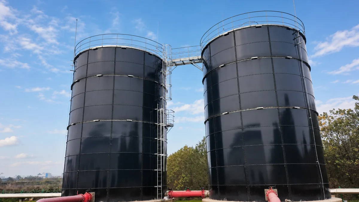
POME storage tank guide covering flow variation, oil and solids, chemistry, equalization, treatment interfaces, access, materials, and RFQ data.
Palm oil mill effluent storage must be considered with actual wastewater data, hydraulic variation, treatment sequencing, access, drainage, and the responsibility boundary between tank and process packages.
POME Storage Is a Process Interface, Not Just a Holding Tank
Palm oil mill effluent, often abbreviated as POME, can vary with mill operation, fruit handling, cleaning activities, oil recovery, rainfall, and the upstream separation process. It may contain suspended material, residual oil, biodegradable organics, and changing temperature or pH conditions. The storage tank therefore has to be matched to actual wastewater characterization and the downstream treatment sequence rather than selected from a generic wastewater volume.
Equalization, buffering, oil separation, anaerobic treatment, solids management, pumping, and odor-control interfaces should be considered together. A tank that is intended to balance intermittent flows needs a defined operating level range, inlet and outlet philosophy, mixing or circulation approach where required, access for inspection, drainage or cleaning route, and a plan for what happens during upset conditions. The project engineer should define these operating cases before equipment is priced.
For broader wastewater selection principles, use the wastewater treatment tank guide. This page focuses on the additional data and interfaces that often arise in palm oil mill effluent duty, including oil and solids management, tropical site conditions, and treatment-plant coordination.
POME Storage and Equalization Inputs
Review area
Information required from the owner or process designer
Influent profile
Average, peak and minimum flow; batch releases; temperature; pH; suspended solids; oil and grease; representative analysis; seasonal variation; and cleaning discharges.
Tank duty
Equalization, temporary storage, oil separation interface, anaerobic feed buffer, sludge holding, emergency containment, or a combination of defined duties.
Hydraulics
Working volume, normal and alarm levels, freeboard, residence time basis, inlet energy, outlet arrangement, bypass, recirculation, pumping, and emergency overflow philosophy.
Materials and corrosion
Wetted chemistry, gases, abrasive solids, cleaning agents, coating or material selection, joints and gaskets, access hardware, and secondary-containment requirement.
Plant interface
Screening, oil recovery, mixing, anaerobic or aerobic treatment, odor control, gas handling, dewatering, electrical and controls scope, and civil drainage.
Characterize the Wastewater Before Selecting Material
POME is not a single fixed chemistry. A supplier needs recent and representative operating data, not only an industry label. The RFQ should identify pH, temperature, conductivity or dissolved salts where relevant, suspended solids, oil and grease, cleaning chemicals, expected gases, abrasive material, microbial conditions, and the maximum rather than only average condition. If the mill is new or is changing process equipment, the designer should issue the design envelope and state the assumptions used for the treatment plant.
Material and coating choice should then be reviewed against the documented duty. This includes the shell, roof, floor, bolts, gaskets, nozzles, internal fittings, instruments, and external access components. A coating description by itself does not establish chemical compatibility. Buyers should request the intended service limits, surface preparation, inspection records, repair procedure, and exclusions as part of the proposal.
Equalization Volume Depends on the Hydraulic Profile
A storage or equalization tank should absorb variation that the downstream process cannot safely accept. The required working volume depends on the time pattern of mill discharges, planned and unplanned cleaning, production peaks, pump availability, treatment capacity, allowable start and stop frequency, and the selected normal and emergency operating levels. A total daily flow alone is not enough to size the tank; the hour-by-hour or batch release profile is usually more valuable.
Inlet and outlet details matter. High-energy inflow can disturb settled material or create localized wear; low-flow zones can allow solids accumulation; and poorly placed outlets can short-circuit the usable volume. The process designer should define whether mixing, recirculation, solids removal, scum management, oil recovery, or a quiescent separation zone is required. These are separate functions and should not be assumed to coexist in one unspecified vessel.
Provide a flow profile, not only a daily total.
State the desired function of each tank and the normal, alarm, and emergency levels.
Coordinate mixing, separation, solids removal, and pumping as defined process duties.
Coordinate the Tank With Treatment and Biogas Interfaces
Where POME enters anaerobic treatment, the upstream storage tank becomes part of the feed-control and safety strategy. The design may need to account for feed consistency, temperature, solids, gas exposure, isolation, drainage, access, and the responsibility boundary between the tank supplier and the treatment-process contractor. The tank does not define digester performance, gas yield, or biological stability; those items belong to the process design and operating data.
If a biogas stage is included, use the biogas and anaerobic digestion application page to map the required gas, membrane, piping, safety, and maintenance interfaces. The enquiry should clearly identify which equipment is included in the tank supply and which is provided by the EPC, process, electrical, or civil contractor.
Plan Access, Cleaning and Site Drainage Early
Wastewater storage needs a safe plan for access, level measurement, sampling, maintenance, isolation, washdown, and any removal of accumulated material. The plan should identify ladders, platforms, handrails, manways, roof access, fall protection, confined-space procedure, lifting points, and the means of keeping stormwater and contaminated water under control. These requirements affect the tank layout and should not be left to a later site adjustment.
For tropical or high-rainfall locations, civil drainage, access roads, crane positions, foundation runoff, erosion control, and weather windows can materially affect installation and operation. A clear responsibility matrix should distinguish tank, foundation, containment, piping, electrical, controls, treatment equipment, installation, testing, and commissioning. The industrial tank installation guide provides a useful starting point for that interface review.
Data to Include in the RFQ
A POME storage RFQ should allow the supplier to confirm the actual wastewater duty, hydraulic range, material or coating basis, treatment interfaces, access package, and supply boundary.
Representative POME analysis, including pH, temperature, suspended solids, oil and grease, cleaning chemicals, gases, abrasive material, seasonal changes, and data source.
Average, peak and minimum flow profile; batch discharges; required working volume; normal, alarm and emergency levels; residence-time basis; and upset scenarios.
Defined tank duty: equalization, storage, oil separation interface, anaerobic feed buffer, sludge holding, emergency containment, or another specified function.
Inlet, outlet, bypass, overflow, pumps, recirculation, mixing, solids or scum management, instruments, sampling, drains, access, roof, and safety requirements.
Project site data, foundation and containment boundary, rainfall and drainage conditions, wind or seismic requirements, transport and lifting constraints, and installation scope.
Nominated material or coating basis, inspection and test plan, document handover, commissioning boundary, operating manual, maintenance data, and spare parts.