Home›Projects›Paper Mill Biogas Gas Holder Project Reference
Paper Mill Biogas Gas Holder Project
Paper mill biogas gas holder project reference covering tank and membrane interfaces, gas conditions, access, safety, installation, maintenance, and RFQ preparation.
This project reference illustrates a bolted tank and membrane gas-holder arrangement; capacity, process performance, pressure limits, location, owner details, and supply boundaries remain specific to the documented project.
A Reference for Reviewing Biogas Storage Interfaces
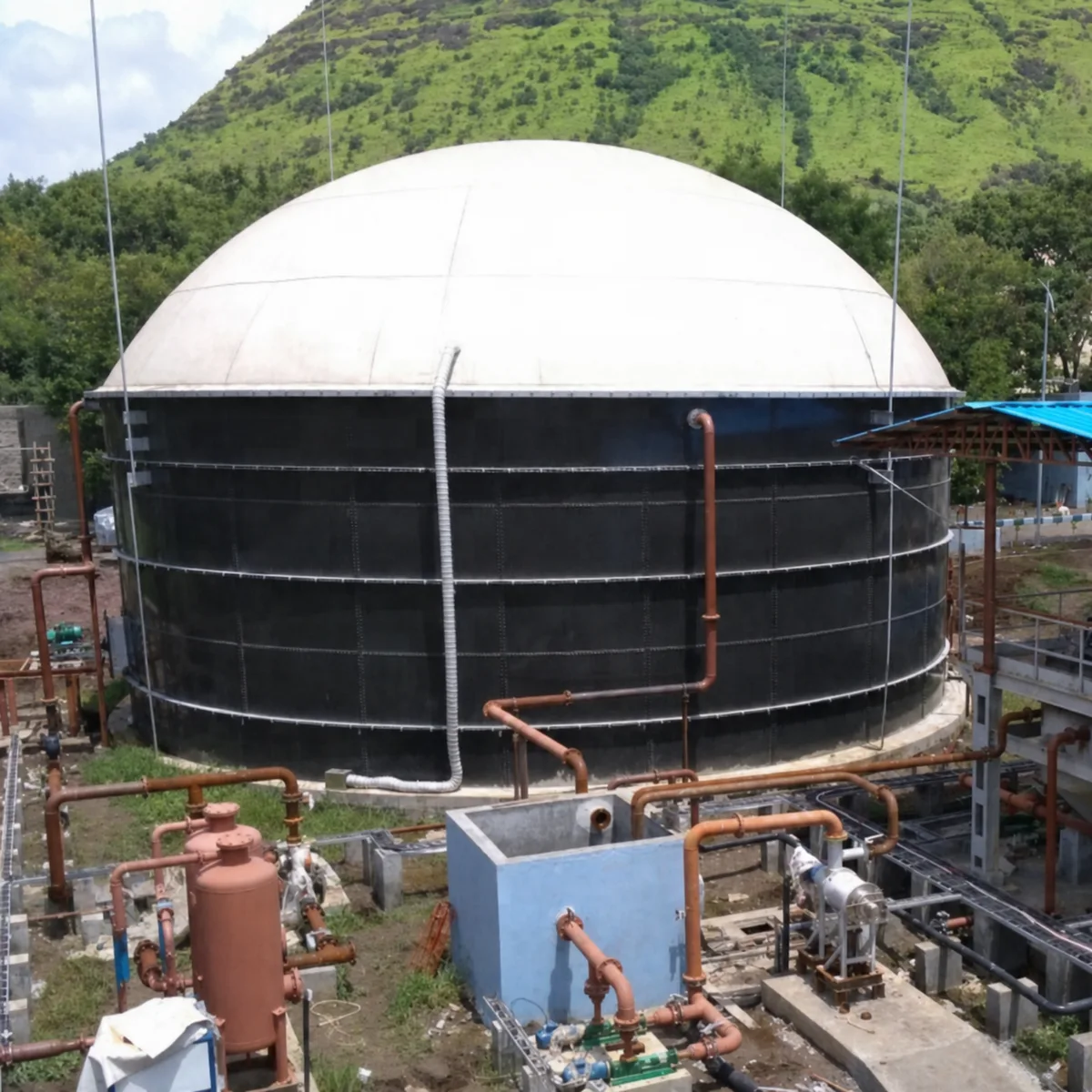
This reference shows a black bolted tank with a white membrane gas-holder arrangement and associated process pipework. It can help buyers frame the design and scope questions for a paper mill or other industrial biogas project: tank duty, membrane arrangement, gas routing, condensate, access, safety, drainage, instrumentation, installation sequence, and maintenance responsibility. It is not evidence of the capacity, gas yield, operating pressure, owner, country, delivery date, or performance of a different project.
Paper and pulp wastewater can have process-specific flow, solids, organic loading, temperature, and treatment characteristics. Whether a gas holder is applicable depends on the actual anaerobic process, gas balance, treatment design, safety study, downstream gas use, and the defined responsibility split between tank, membrane, gas-treatment, electrical, control, civil, and EPC contractors. Those data must be issued by the project team before a comparable system is designed or quoted.
Information required before using a comparable arrangement
Wastewater and process
Paper mill process streams, wastewater analysis, flow variation, pretreatment, solids handling, anaerobic design basis, feed control, and operating scenarios.
Gas system
Expected generation range, gas composition, normal and maximum pressure, vacuum case, condensate, relief, isolation, treatment, flare or end use, and hazardous-area classification.
Tank and membrane
Tank geometry, operating level, membrane type and duty, attachment details, drainage, access openings, roof loads, inspection method, and repair route.
Design basis, drawings, calculations, material and membrane records, inspection and test plan, method statements, operating limits, manuals, spares, and handover data.
The Visible Tank Is Only One Part of the Process
A project photograph can show a tank, membrane cover, and pipework, but it cannot show the process assumptions that make the system safe and operable. The project team must define wastewater source, pretreatment, anaerobic process, feed control, gas-generation variability, composition, pressure-control philosophy, condensate management, treatment equipment, emergency conditions, and downstream use. A supplier should not infer these parameters from a similar industrial sector or a previous installation.
The same caution applies to the supply boundary. Tank shell, membrane, gas piping, blowers, flare, gas treatment, controls, electrical work, foundations, installation, testing, and commissioning are often divided across contractors. The contract should state who designs, supplies, installs, tests, and accepts each interface. A complete proposal identifies those boundaries instead of treating a visible roof package as a complete biogas system.
Gas Safety and Pressure Control Need Project-Specific Data
Membrane gas storage must be evaluated using the actual pressure and volume envelope, gas composition, gas-cleaning requirements, isolation and relief arrangement, condensate points, instrumentation, emergency response, and applicable site safety rules. A membrane cover does not independently establish a safe operating pressure or relieve the owner of a process hazard review. The design basis must be approved by the responsible project engineer and reflected in the equipment interfaces.
The RFQ should distinguish normal, maximum, and abnormal operating states. It should also identify vacuum risk, flare or end-use availability, gas analyzer interfaces, electrical classification, lightning protection, access controls, and maintenance isolation. The industrial tank RFQ data checklist can be used to organize these inputs alongside the process documents.
Issue the gas balance and safety basis before requesting membrane sizing.
Separate tank scope from gas cleaning, compression, flare, controls, and civil work.
Do not use a project image to infer pressure, capacity, performance, or owner information.
Installation and Maintenance Are Design Inputs
The project team should determine how tank panels, membrane components, pipes, platforms, lifting equipment, and temporary works will reach the site and be assembled. Ground conditions, weather, lifting radius, storage space, foundation readiness, utilities, installation access, and safe work zones can determine whether an otherwise suitable configuration can be executed. These constraints belong in the bid package and construction method, not in a late-stage site instruction.
Long-term planning includes membrane inspection, roof and ladder access, gas isolation, drainage, condensate handling, inspection records, replacement materials, and defined response procedures for abnormal conditions. Align the final plan with the site's approved installation and safety requirements.
Use the Reference Without Overstating the Evidence
This case is a useful reference for the physical relationship between a bolted tank, membrane gas holder, pipes, and access equipment. It should be used to develop questions for a new project, not to copy unverified dimensions, capacity, gas quality, production performance, schedule, supplier scope, or compliance claims. The next project needs its own documented process, civil, mechanical, electrical, and safety basis.
A comparable proposal should list all accepted inputs, deviations, exclusions, testing, commissioning requirements, and document deliverables. That gives buyers a meaningful way to compare suppliers and makes it clear which performance or safety obligations sit with the tank package and which remain with the process or EPC team.
Data to Include in the RFQ
A gas-holder RFQ should connect the documented process and gas basis with tank geometry, membrane interfaces, site constraints, installation responsibilities, inspection, and handover requirements.
Paper mill wastewater and anaerobic process basis, feed profile, gas generation range, composition, normal and maximum pressure, vacuum case, condensate, treatment, flare or end use.
Tank dimensions and operating levels, membrane duty and attachment concept, roof access, drainage, inspection openings, ladders, platforms, instruments, and fall protection.
Foundation, anchor, lifting, temporary works, installation route, site access, weather exposure, utilities, piping supports, electrical and controls interfaces.
Safety and operating controls, isolation, relief route, hazardous-area information, gas detection, emergency response, roof access restrictions, and maintenance procedure.
Defined scope split among tank supplier, membrane supplier, process contractor, gas-treatment package, civil contractor, electrical and controls contractor, installer, and owner.
Required calculations, drawings, material and membrane records, inspection plan, test and commissioning scope, manuals, spare parts, training, warranty boundary, and handover documents.