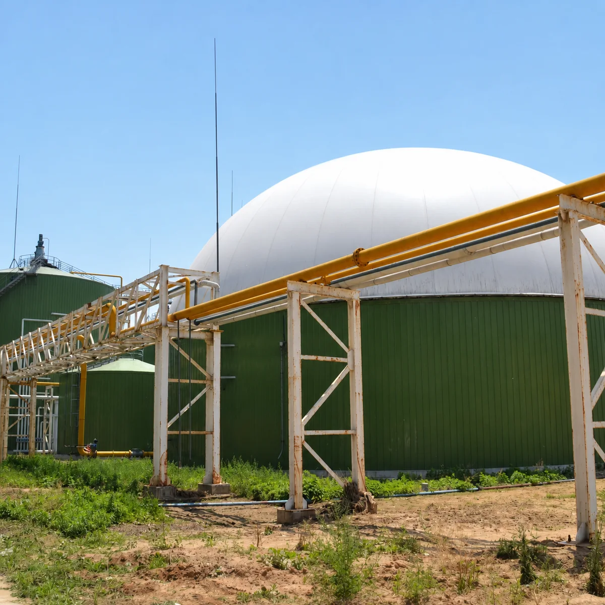
Biomethane gas holder checklist for gas conditions, pressure and vacuum cases, condensate, safety, process boundaries, access, and RFQ data.
Gas-holder selection depends on the documented gas balance, pressure and vacuum envelope, condensate controls, safety study, and defined process interfaces.
Define the Gas Holder Within the Whole Gas System
A gas holder is one element in a biogas or biomethane project, not a stand-alone performance guarantee. Its required volume, pressure envelope, membrane arrangement, attachments, instrumentation, condensate controls, access, and operating procedures depend on the upstream digestion process and the downstream upgrading, compression, storage, flare, grid-injection, vehicle-fuel, or end-use system. The project team must issue those interfaces before a supplier can responsibly confirm a gas-holder concept.
Biogas and biomethane should not be treated as interchangeable descriptions. Raw biogas may need cleaning, drying, pressure control, and composition monitoring before an upgrading system; biomethane may have a separate quality, compression, metering, and delivery arrangement. The exact process sequence, gas composition range, flow range, pressure and vacuum cases, temperature, condensate behavior, relief philosophy, hazardous-area classification, and shutdown scenarios belong in the project design basis.
Use the biogas and anaerobic digestion application guide to map the broader process. This checklist concentrates on information needed to connect a membrane gas holder or related gas-storage interface without guessing at performance or safety obligations.
Gas Holder Interface Checklist
Interface area
Information required from the project team
Gas source and balance
Digester or process source, expected minimum, normal and maximum generation, hourly variation, startup and upset cases, planned turndown, and downstream availability.
Gas condition
Composition range, moisture and condensate behavior, contaminants, temperature, pressure, vacuum risk, sampling, analysis, treatment sequence, and approved operating limits.
Holder duty
Required buffer function, usable volume basis, pressure and vacuum envelope, membrane arrangement, roof or tank connection, access, drainage, and maintenance method.
Safety and controls
Isolation, relief route, flare or end-use availability, gas detection, electrical classification, lightning protection, emergency shutdown, permits, access controls, and response plan.
Project boundary
Tank or structure, membrane, blowers, gas treatment, pipes, controls, electrical works, civil work, installation, testing, commissioning, documentation, and performance responsibilities.
Separate Process Performance From the Storage Interface
A photograph of a membrane dome or a previous installation cannot establish the required gas-holder volume, pressure, gas quality, or production performance for a new plant. Those values come from the project gas balance and process design. The owner or EPC team should issue expected generation range, hourly variation, minimum and maximum operating cases, planned shutdowns, downstream consumption or upgrading availability, flare strategy, and desired buffer function. Only then can a supplier assess an interface rather than infer a duty from a sector label.
The scope must distinguish raw gas, treated gas, and final biomethane where relevant. Each may have different composition, moisture, contaminants, pressure, measurement, and safety requirements. State the physical battery limits, ownership of gas-treatment equipment, location of analyzers and isolation valves, and the party responsible for confirming the acceptable gas condition at every interface. This prevents a membrane or tank supplier from being assigned unpriced process obligations.
State Normal, Maximum and Vacuum Cases
A credible design basis identifies normal operation as well as high-pressure, low-pressure, vacuum, blocked-flow, utility-loss, maintenance, and emergency cases. The project safety review should define the approved relief and isolation philosophy, rather than assuming that a membrane roof or a nominal vent opening solves every scenario. The final equipment design has to be checked by the responsible engineer against the governing project requirements and actual interfaces.
Pressure and vacuum information should be issued with the associated measurement and control strategy. Include instruments, alarm and trip responsibilities, manual and automatic isolation, flare or alternate disposal path, downstream compression availability, power-failure response, condensate effects, and who receives and acts on abnormal signals. The gas holder, pipework, treatment equipment, and control system are connected parts of one safety-critical arrangement.
Provide a written operating envelope rather than one nominal pressure.
Identify vacuum exposure during cooling, withdrawal, isolation, cleaning, or abnormal operation.
Show relief, isolation, flare, detection, and control responsibilities at actual battery limits.
Control Condensate, Access and Site Interfaces
Water and condensate management can affect gas flow, corrosion, instrumentation, inspection, and maintenance. The bid package should identify low points, drains, traps, slopes, heating or insulation where specified, access restrictions, disposal route, freeze exposure if relevant, and the operating procedure for servicing components. The supplier must know whether condensate systems are inside or outside the gas-holder package and what site utilities or drainage connections are available.
Access also needs a defined plan. Membrane inspection, roof or tank access, ladders, platforms, fall protection, lifting, electrical isolation, permits, weather limits, and emergency response are site-specific. No temporary equipment, cable route, maintenance platform, or pipe support should be attached without checking the approved load basis. For configuration context, see the double membrane roof product page.
Build an RFQ That Can Be Compared
A well-defined RFQ states gas conditions, holder duty, mechanical arrangement, site constraints, supply boundary, inspection plan, documents, installation method, testing, commissioning, and warranty limits. It also identifies whether the offer is for a membrane only, a holder integrated with a tank, a complete package with selected interfaces, or engineering support. Suppliers should list assumptions, exclusions, and required owner inputs so bids can be compared technically as well as commercially.
The final document set should identify drawings, calculations where included, membrane material information, attachment details, inspection and test plan, installation instructions, operating limits, maintenance requirements, spare parts, and handover records. Use the industrial tank RFQ data checklist to coordinate this information with tank, civil, process, electrical, and control disciplines before award.
Data to Include in the RFQ
A biomethane gas-holder RFQ needs the documented gas balance and safety basis, then connects those data to the membrane, tank, process, site, installation, and handover interfaces.
Process source, gas-generation range and time profile, composition, temperature, moisture, contaminants, treatment sequence, normal and maximum pressure, vacuum cases, and downstream use or flare strategy.
Required buffer function, usable volume basis, holder or membrane configuration, attachment concept, roof or tank interface, access, drainage, inspection, maintenance, and replacement route.
Isolation, relief, pressure and vacuum control, condensate management, gas detection, hazardous-area information, electrical and controls interfaces, emergency shutdown, permits, and response procedures.
Foundation or tank interface, site layout, lifting, storage, weather exposure, utilities, drainage, pipe supports, installation sequence, temporary works, and responsibility boundary.
Required calculations and drawings, material and membrane records, inspection and test plan, installation instructions, commissioning scope, operating manual, maintenance data, spares, training, and warranty boundary.