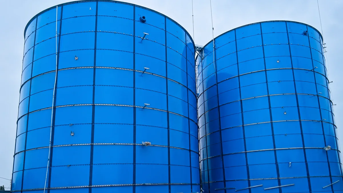
Prepare FBE bolted tank foundations with project loads, survey tolerances, drainage, anchors, settlement, access, erection sequence, and RFQ scope.
Foundation design for an FBE bolted tank must be coordinated with tank reactions, tolerances, drainage, erection access, and the civil design basis.
Foundation Data Is Part of the Tank Design Input
A fusion-bonded epoxy bolted tank does not arrive with a universal foundation drawing that can be reused without project review. The tank supplier, civil engineer, EPC contractor, and owner need a defined interface covering tank geometry, operating levels, liquid density, wind and seismic basis, roof and accessory loads, anchors where applicable, settlement criteria, drainage, access, and the erection sequence. The foundation must support the complete operating tank, not only the empty shell footprint.
The civil design remains the responsibility of the qualified project engineer and must follow the governing local code, geotechnical information, and site conditions. The tank supplier should provide the required reactions, footprint, anchor or hold-down requirements if applicable, tolerance requirements, and installation constraints. The civil team should then confirm soil bearing, settlement, reinforcement, drainage, elevation, and constructability. Neither party should infer the other party’s design scope from a generic drawing.
Diameter, shell height, gross and usable capacity, liquid density, roof type, accessories, operating levels, internal equipment, and future additions.
Site conditions
Survey level, soil report, groundwater, frost or expansive-soil risk where relevant, seismic and wind basis, drainage path, and adjacent structures.
Foundation geometry
Foundation type, finished diameter, elevation, slope or flatness requirement, edge condition, penetrations, embedded items, and perimeter drainage.
Loads and movement
Empty, operating, test, wind, seismic, roof, platform, pipe, mixer, and equipment loads; allowable settlement and differential settlement criteria.
Erection and handover
Crane and delivery access, panel staging, anchoring sequence, field measurement, tolerance verification, test-water plan, and as-built documentation.
Give the Civil Engineer the Complete Tank Package
Tank reactions can change when the stored liquid density, roof, internal equipment, access platforms, external piping, insulation, ladders, or wind and seismic basis changes. The civil engineer needs the current tank data, not a preliminary capacity note. The tank supplier should issue a controlled interface package and should identify assumptions, revisions, and items that are outside the standard tank scope.
The owner should also identify possible future changes such as a different stored medium, higher operating level, larger mixer, roof-mounted equipment, new pipe rack, or additional platform. Designing only for the first operating case can make future modification expensive or unsafe. If future changes are uncertain, the project should define a formal review point before civil works are released.
Flatness, Elevation, and Settlement Affect Assembly
Bolted tank panels and sealed joints require a foundation that meets the supplier’s specified tolerance. Excessive local high points, edge irregularities, differential movement, or poor drainage can affect shell alignment, base seal, nozzle orientation, roof fit, and long-term operation. The tolerance must be stated in the approved project documents; it should not be guessed from a photograph or from another tank diameter.
Foundation verification should occur before panels are erected and again at defined construction stages when the project requires it. Survey records, finished elevation, perimeter condition, drain locations, penetrations, and any repaired areas should be documented. If the measured foundation falls outside the agreed tolerance, the civil and tank teams should resolve it before assembly rather than trying to correct geometry through panel force or sealant alone.
Confirm the specified survey grid and acceptance method before concrete placement.
Keep drains, conduits, embedded plates, and penetrations coordinated with the approved tank drawing.
Protect the finished surface from damage during deliveries, staging, and lifting operations.
Plan Drainage, Water Testing, and Site Access
Surface water around the tank should drain away without undermining the foundation, flooding access routes, or creating a standing-water condition against the shell. The tank arrangement should coordinate site grades, perimeter drains, containment if required, roof runoff, test-water handling, and the route for any future washdown or maintenance water. These features depend on the project drainage plan and cannot be standardized across climates or jurisdictions.
Erection access also matters. Panel delivery, unloading, cranes, scaffolding, temporary storage, work platforms, electrical supply, lighting, safety exclusion zones, and test-water supply or disposal should be planned before construction begins. The tank installer needs a safe and stable work area; the civil contractor needs to know what temporary loads and access constraints the erection team will create.
Keep Civil and Tank Scope Traceable
A responsibility matrix should identify who provides the geotechnical report, foundation design, reinforcement drawings, concrete placement, survey verification, anchors, embedded items, site drainage, access road, crane hardstanding, erection, hydrostatic testing, water supply, discharge approval, and as-built records. The matrix should also identify the review and release sequence between the civil contractor, tank supplier, installer, EPC team, and owner.
Coating-system selection and handling should follow the approved product and installation requirements. For final procurement data, use the RFQ data checklist. Clear interfaces reduce late changes, claims, and attempts to assign foundation responsibility after the tank is already on site.
Issue the latest tank data before the civil design is frozen.
Record foundation measurements and acceptance before tank assembly.
Keep design assumptions, revisions, tests, and handover documents together in the project record.
Use Project-Specific Engineering for Non-Standard Conditions
Unusual soil, high groundwater, seismic demand, flood exposure, corrosive soils, insulated tanks, heavy process equipment, elevated tanks, or aggressive operating cycles may require additional geotechnical, structural, or mechanical analysis. Those conditions should be identified early because they can affect tank configuration, anchors, base details, civil schedule, and cost. A standard detail may not address a non-standard site condition.
The correct outcome is a coordinated design package with documented assumptions. A tank quotation should state the foundation data it relies on, and the civil design should state the tank loads and tolerances it adopts. This traceable exchange is more valuable than a generic assurance that a foundation is “suitable.”
Data to Include in the RFQ
Send foundation and site information early so the tank and civil teams can confirm interface requirements before procurement or concrete works begin.
Tank diameter, height, capacity, liquid density, operating levels, roof, accessories, internal equipment, external piping, and future loads.
Project location, survey, geotechnical report, groundwater, wind/seismic basis, ambient conditions, site grades, and drainage plan.
Proposed foundation type, finished elevation, diameter, slope or flatness target, anchors/embedded items, penetrations, and perimeter details.
Allowable total and differential settlement criteria, construction-stage survey requirements, and responsible engineering party.
Site access, delivery/staging area, crane hardstanding, temporary works, erection sequence, test-water supply/disposal, and safety constraints.