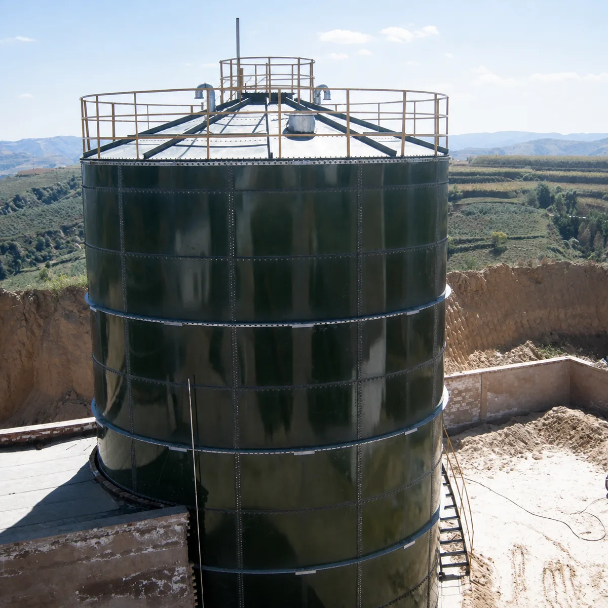
Application guide for biogas gas holders serving palm oil processing facilities, covering gas balance, composition, condensate, controls, safety interfaces, installation, and RFQ data.
A palm oil processing gas holder should be specified from the actual gas balance and plant interfaces, not from a nominal storage volume alone.
Gas Storage Must Follow the Plant Gas Balance
Palm oil processing can generate organic wastewater and residues that are treated through an owner-defined process train. Where anaerobic treatment is used, gas generation can vary with influent characteristics, temperature, loading, retention, maintenance, and plant operation. A gas holder may provide temporary buffer volume between generation and downstream treatment, use, flare, upgrading, or compression. It is not a substitute for a complete gas-treatment, safety, emissions, or process-performance design. The project needs a time-based gas balance, representative gas data, operating and upset conditions, pressure limits, and a defined responsibility matrix before a holder can be selected responsibly.
For the wastewater-side storage and treatment context, see the palm oil mill effluent storage page. This application page addresses the gas holder and its interfaces after gas reaches the defined collection point. The responsible process and safety teams must confirm the final arrangement against the facility, its operations, and applicable local requirements.
Palm Oil Biogas Gas-Holder Inputs
Review area
Information required for a comparable proposal
Gas balance
Minimum, normal, peak, and upset gas-generation profile; buffer objective; downtime; downstream demand; flare or alternate disposal path; and the required operating sequence.
Gas condition
Methane and carbon-dioxide range, oxygen, hydrogen sulfide, moisture, temperature, condensate, particulates, treatment location, sampling basis, and expected variation.
Holder and controls
Usable buffer basis, selected holder or membrane configuration, pressure and vacuum limits, isolation, control equipment, alarms, relief, detection, maintenance, and emergency responsibilities.
Site interface
Tank or foundation interface, access, drainage, utilities, electrical and controls boundary, lifting, weather exposure, installation, tests, documents, and commissioning scope.
Build the RFQ Around a Time-Based Gas Balance
A nominal daily gas volume does not establish the holder duty. The enquiry should show the minimum, normal, peak, and upset generation profile; the expected buffer duration; downstream consumption, upgrading, or compression profile; planned shutdowns; and what happens when the holder reaches high or low operating limits. This information allows the project team to distinguish a buffer need from a throughput, treatment, or disposal issue that must be solved elsewhere in the plant.
The scope must identify where raw gas enters the holder and which equipment lies upstream and downstream. Desulfurization, dehumidification, condensate removal, carbon-dioxide treatment, compression, flare equipment, utilization equipment, pipework, valves, and controls may belong to different packages. The commercial scope should state whether the requested item is a holder only, a holder attached to a tank, or a broader package with explicitly listed interfaces.
Use Real Gas Data for Materials and Operating Assumptions
Biogas composition can change with feedstock and process conditions. Methane, carbon dioxide, hydrogen sulfide, oxygen, moisture, condensate, temperature, and particulate information should come from the project sampling and process basis. These conditions can affect material selection, membrane or cover suitability, gaskets, drains, instrumentation, corrosion exposure, inspection frequency, and the design of connected equipment. A gas holder should not be specified from a different feedstock or treatment train without a documented review.
Condensate is an operating issue as well as a materials issue. The owner should define low points, drains, traps, heat tracing or insulation if specified, access for cleaning and maintenance, safe disposal route, and the boundary between holder equipment and associated gas pipework. Standing liquid, blocked drains, and inaccessible instruments can turn a nominally suitable storage volume into a difficult-to-operate system.
Coordinate Holder Configuration With the Tank and Gas System
The selected gas-holder configuration should be evaluated with the underlying tank, roof connections, pressure envelope, access arrangement, attached loads, wind and weather exposure, isolation points, and maintenance route. The buyer should identify whether a roof, membrane, support system, blower, pressure-control equipment, or tank shell is within the requested supply boundary. This prevents one party from pricing equipment that assumes another party will solve structural or control interfaces later.
For configuration context, compare the project duty with the single and double membrane roof page. The page provides a starting point for terminology and RFQ preparation; final selection must follow approved calculations, gas data, site constraints, and the project safety review.
Make Safety and Control Boundaries Explicit
Pressure and vacuum limits, isolation, relief, alarms, detection, emergency shutdown, electrical interfaces, hazardous-area basis where applicable, and manual response arrangements must be identified by the responsible project team. The holder, pipework, treatment equipment, and controls are connected systems. No single component should be assumed to provide a facility-wide safety function unless that function and its acceptance method are explicitly included in the approved design.
The design review should also identify test points, calibration access, emergency access, inspection intervals, maintenance isolation, weather exposure, and the records required before gas is introduced. Installation can require lifting, temporary works, safe access, weather protection, and a clear sequence with the civil, tank, electrical, and process teams. These practical interfaces should be included in the RFQ rather than left to site interpretation.
Compare Proposals on Their Complete Boundary
Before award, compare gas balance assumptions, composition data, usable buffer basis, holder configuration, pressure and vacuum limits, tank or roof interface, accessories, controls, safety interfaces, site works, installation, inspection, testing, commissioning, documents, and exclusions. A proposal should explain what it supplies, what data it relies on, and what remains with the owner, EPC contractor, installer, or other package supplier.
Use the industrial tank RFQ data checklist to issue one coordinated enquiry covering process, mechanical, civil, electrical, controls, safety, site, and documentation inputs. The result should be a transparent gas-holder scope that can be compared technically and commercially without implying plant performance or compliance that has not been engineered and approved for the facility.
Data to Include in the RFQ
A palm oil processing biogas gas-holder RFQ should start with a time-based gas balance and representative gas data, then define holder, tank, safety, controls, site, installation, and handover interfaces.
Minimum, normal, peak, and upset gas profile; required buffer objective and duration; gas source; downstream treatment, upgrading, compression, use, flare, and planned downtime.
Gas composition, moisture, condensate, temperature, contaminants, representative analysis, treatment sequence, pressure and vacuum limits, and owner-approved compatibility basis.
Holder configuration, tank or roof interface, access, drains, isolation, valves, controls, alarms, detection, relief, electrical boundary, hazardous-area information where applicable, and emergency responsibilities.
Foundation or tank interface, site access, lifting, weather, drainage, utilities, installation, inspection, testing, commissioning, documents, spares, operating limits, and acceptance requirements.